 Husbryg
 Putting the Pressure Monitor Hardware Together
It is now time to find the various components needed to build the pressure monitor described in this previous post.
I have already decided to run this from the same Raspberry Pi Model 3 B that also runs the Tilt Pi setup. You can probably run this from even smaller models too such as the Zero.
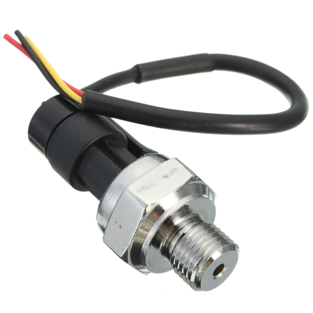
I searched around on various internet sites for a pressure sensor in the 0 – 3 bar range. But I didn’t manage to find any cheap ones. The cheapest sensor I could find was a 5 VDC 0 – 12 bar sensor. The same type of sensor is also available in a 0 – 5 bar version, but slightly more expensive. Generally they need a 5 VDC supply and then output between 0,5 and 4,5 V on the signal wire. They are rated with a measurement accuracy of 1% which is 0,12 bar or 0,05 bar respectively.
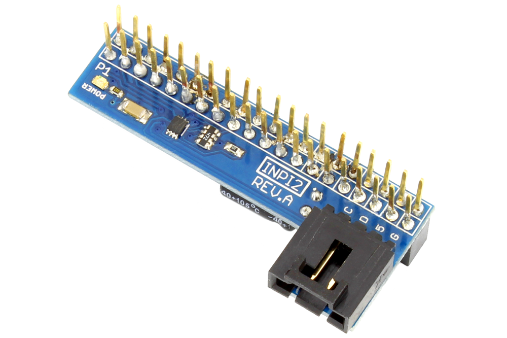
I wanted to find and Analog-to-Digital converter that was easy to setup and configure. There are several models available, but I decided to go for one based on the ADC121C021 chip from Texas Instruments. It’s a 12 bit single channel ADC using I2C for communication so it should be fairly easy to integrate with the Raspberry Pi. I found a module from NCD that uses this chip and also provides 5 VDC output for the pressure transducer. Same company also makes an expansion module for the 40-pin connector on the Raspberry Pi so no soldering needed for my part as it just connects via existing pins and cables.
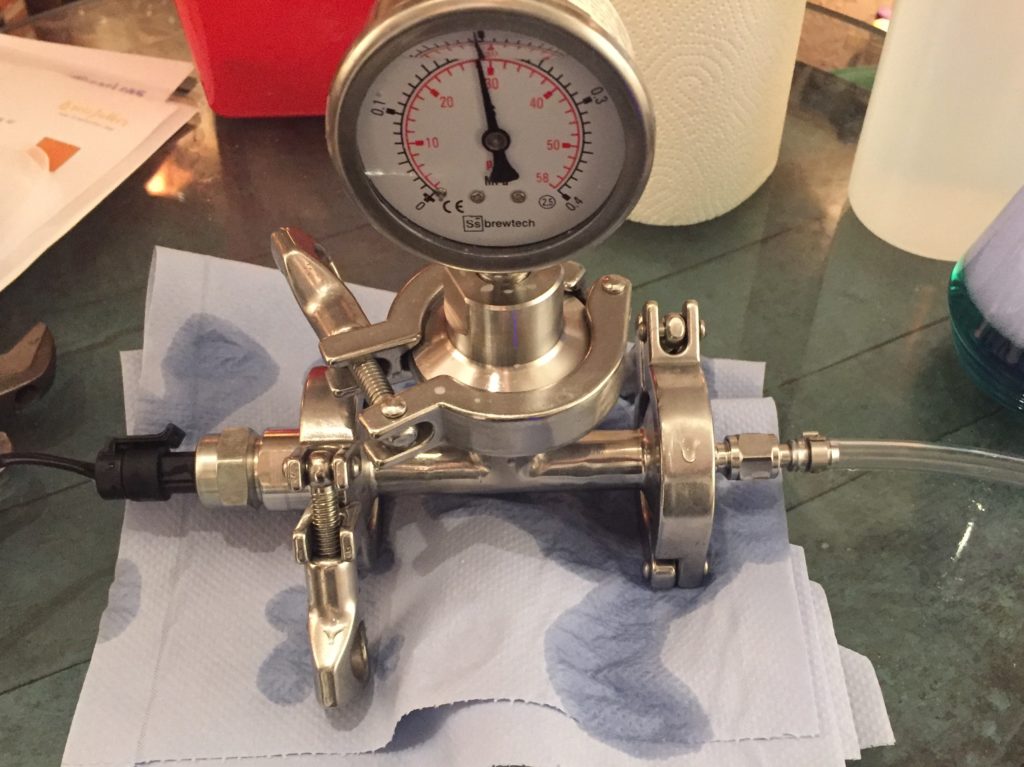
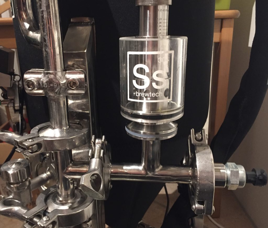
The final piece of the puzzle is the mounting of the pressure sensor on the unitank. I already had planned to put it somewhere near the spunding valve. It is already mounted on a 90° elbow connection so by replacing this with a tee connection I would get a spare tri-clamp connection for the sensor. It took a bit of searching but I managed to find a tee-connection as well as a tri-clamp flange with a 1/4″ threaded connection for the pressure sensor.
Once all the parts arrived it was time to put them together and make sure everything connected as expected. One of the problems I discovered was the thread for the pressure sensors. It was specified as a 1/4″ NPT thread which by definition means it’s tapered. However the threads on the sensors are all straight. Besides that, there are fairly large differences between the two sensors I got. Because of that, I have not managed to get the 0-5 bar sensor to seal completely, so I am currently building the setup using the 0-12 bar sensor. It provides a bit less accurate readings, but it should be OK for the purpose.
Everything is now connected to together and it’s time for the coding of the Node RED monitor flow. I’ll cover that in a future blog post.
Parts List
To sum it all up, these are the parts I ended up using for building the pressure monitor.
 | I2C Shield for Raspberry Pi (NCD) |
| ADC121C021 1-Channel 12-Bit Analog to Digital Converter (NCD) | |
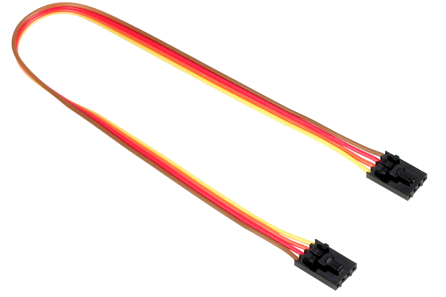 | I2C Cable (0,5 m) (NCD) |
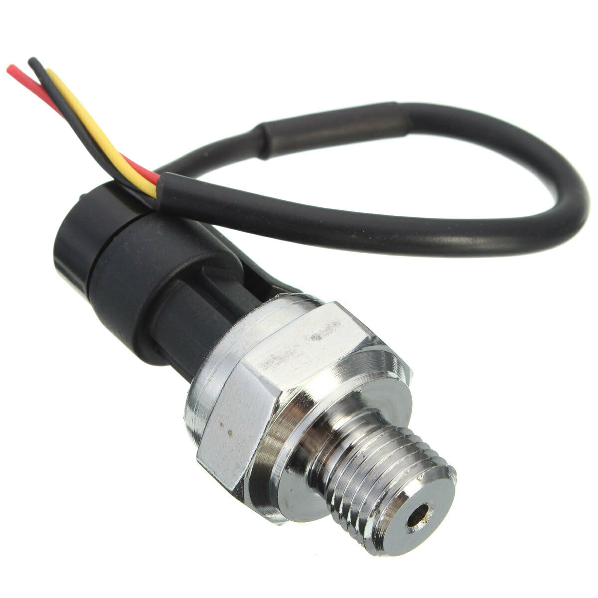 | 5V DC Pressure Transducer Sensor 0-1,2 MPa (eBay) or 0-0,5 MPa (eBay) |
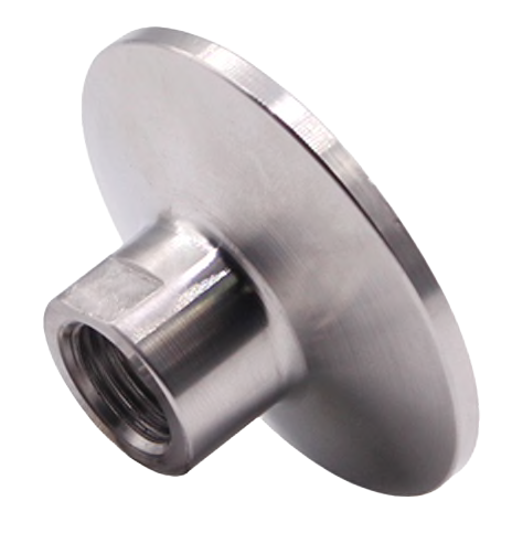 | 1/4” NPT Female Thread Pipe Fittings x 1.5″ Tri Clamp (Ali Express) |
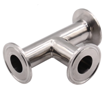 | 1.5″ OD 25MM Tri Clamp Stainless Steel 3 Way Tee (Ali Express) |
There is a fair chance that some of the items from eBay and Ali Express are probably no longer available from that seller. But they should be fairly easy to find from other sellers too.
Hope you enjoyed the post and found it useful. Please add your comments, questions or suggestions below.
2 Replies to “Putting the Pressure Monitor Hardware Together”
Hey Buddy, first of all, congratulations on the amazing blog.
Did you know any replacement parts for the I2C, ADC121C021 and cable from AliExpress? The shipping from NCD to New Zealand is nuts.
Thank you so much for this blog. I will read it all.
I have a glance and saw you are a GF guy. Any change you will working on the BrewZilla as well?
CHeers
Marcelo
I searched on AliExpress and eBay for these components, but didn’t manage to find any.
If you search for alternatives, you should look for components that supply 5V to the sensor. It should be possible to find other ADC’s but some of these have differential input instead of the ADC121C021’s input referenced to GND